|
|
|
|
|
|
|
|
|
|
|
|


Spectrum-RG/eRosita/Lobster
Roscosmos
ESA
Space Research Institute, IKI,
Max-Planck-Institute
for extraterrestrial Physics, MPE,
September 2005
Signed, September 30th, 2005
Gennady Dmitriev, Roscosmos, Head of Department
Günther Hasinger, MPE Garching, Director of High-Energy
Astrophysics
Arvind Parmar, ESA Representative
Mikhail Pavlinsky, IKI, Deputy Director for Science
George Fraser, LU, Director of
contents
4.1 Soyuz LV main
characteristics
4.2 FREGAT payload assist
module
5.2 Navigator (Lavochkin
Association)
1.
mission overview
The
baseline configuration of the new SRG mission was defined to be as following:
-
Soyus-2
launch in the 2009-2010 timeframe from Kourou into a
-
Medium
class spacecraft would be perfectly suitable for the mission, such as Yamal,
which has been extensively operated in space, or Navigator;
-
Wolter-telescopes
eROSITA (extended ROentgen Survey with an Imaging Telescope Array, MPE,
The
mission will conduct the first all-sky survey with an imaging telescope in the
2-12 keV band to discover the hidden population of several hundred thousand
obscured supermassive black holes and the first all-sky imaging X-ray time
variability survey. In addition to the all-sky surveys it is foreseen to
observe dedicated sky regions with high sensitivity to detect ten thousands of
clusters of galaxies and thereafter to do follow-up pointed observations of
selected sources, in order to investigate the nature of Dark Matter and Dark
Energy. The proposed orbit provides an order of magnitude lower particle
background than those of Chandra and XMM-Newton, which will allow the detailed
study of low-surface-brightness diffuse objects.
Both eROSITA
and Lobster were previously studied and endorsed by ESA for the International
Space Station. Their accommodation on a dedicated free flyer would provide
significantly improved scientific output.
The eROSITA
telescopes are based on the existing design launched on the (unfortunately
failed) ABRIXAS mission and flight-ready detectors have been fabricated, which
guarantees the high sensitivity required for the broad band all-sky survey. In
order to optimise eROSITA for the additional science goal of the Dark Energy
study, it is highly desirable to increase the grasp and improve the angular
resolution of the X-ray telescopes. The group asked MPE to undertake
feasibility studies for such improvements. The improved capabilities would
respond to scientific developments of the last years; they e.g. match well the
goals set out in the recent call for ideas on Dark Energy observations.
For
Lobster, for which a detailed ESA Phase-A study has been successfully
completed, it may be possible to increase the focal length of the micropore
optics, thus improving the high-energy response.
The new
SRG mission would thus be a highly significant scientific and technological
step beyond Chandra/XMM-Newton and would provide important and timely inputs
for the next generation of giant X-ray observatories like XEUS/Con-X planned
for the 2015-2025 horizon. A timely launch of SRG in the 2009-2010 period will
help to sustain the high levels of technological and scientific expertise in
European and Russian astronomy, and supply both communities with large bodies
of high-quality data.
The
following contributions by the different partners will be sought:
-
Provision
of the Soyus-2/Fregat launch vehicle by Roscosmos;
-
Provision
of a space tested platform by Roscosmos;
-
Provision
of the eROSITA instrument by the German-led consortium;
-
Provision
of the Lobster instrument by the UK-led consortium;
-
Provision
of the ART instrument and Gamma-Ray Burst detector by Roscosmos (IKI-led
consortium);
-
Contribution
by ESA to the Kourou launch operations;
-
Contribution
by ESA to the telemetry system;
-
Contribution
by ESA to the ground station support.
2.
 scientific Payload
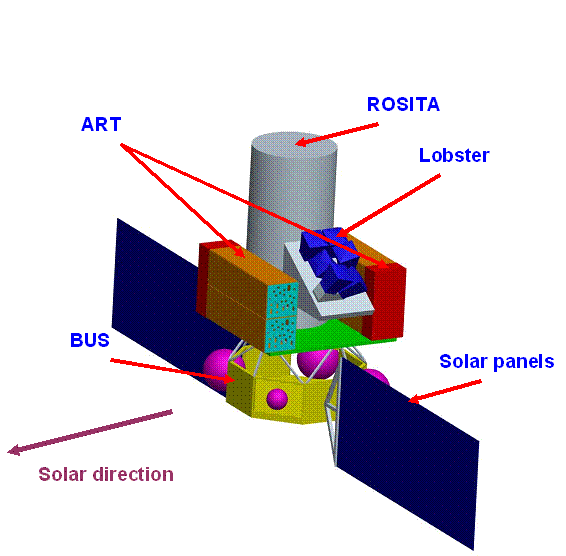
![]()
Scientific
payload:
-
eROSITA
(MPE, Germany), Wolter-telescopes, 7 mirror systems, size of individual
ROSITA-Telescopes –
-
Lobster
(LU, UK), wide field x-ray monitor, 6 modules, energy range 0.1 - 4.0 keV
(TBD), angular resolution 4¢
(FWHM), energy resolution DE/E ~20%, a grasp of ~104 cm2 deg2 at 1 keV, ~0.15 mCrab daily sensitivity, FOV
22.5°´162°, mass
-
ART
– Astronomical Roentgen Telescopes (IKI, Russia), imaging coded mask
telescopes, consist of 2 telescopes (ART-X) for 3-30 keV energy range and 2
telescopes (ART-HX) for 20-120 keV energy range, FOV of each telescope 10°´10° (TBD), angular resolution £3¢ (TBD) (ART-X) and £9¢ (TBD) (ART-HX), detector effective
area ~103 cm2 (each), energy resolution 1.2 keV
at 6 keV (ART-X), 3 keV at 60 keV (ART-HX). Two units with mass –
-
GRB
– Gamma-Ray Burst detector (IKI,
-
BIUS
– on-board computer (IKI,
PL mass –
PL power
consumption – 600 W (100 W margin).
3.
Scientific
objectives
3.1
eROSITA
3.1.1 Science
X-rays
are a powerful diagnostic tool to study the physical universe, because the
strongest gravitational potentials (clusters, black holes) heat up matter to
X-ray temperature and a significant fraction of the baryons in the Universe is
in the form of hot gas which can only be observed in X-rays. X-rays can
penetrate gas and dust which obscure significant portions of galaxies.
Relativistic effects and the extreme physics of the nucleonic equation of state
can be diagnosed in the X-ray regime. The K-shell transitions of almost all
chemical elements occur in the X-ray regime, which thus allows the study of the
creation of the elements over cosmic time. Wide field deep X-ray surveys are
dominated by active galactic nuclei, diffuse emission in clusters of galaxies
with some contribution from galactic stars.
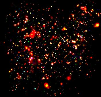
Figure 3.1.1: XMM-Newton Survey of the COSMOS field. The solid
angle of 2°´2° and sensitivity make this the
deepest wide field X-ray survey ever performed. Point sources (AGN) and
extended emission (clusters of galaxies) can be readily distinguished. The
surveys planned with eROSITA are expected to yield a similar composition over
huge solid angles on the sky.
3.1.1.1
The
quest for Dark Energy
The nature of the mysterious
Dark Energy that is driving the Universe apart is one of the most exciting
questions facing astronomy and physics today. It may be the vacuum energy
providing the Cosmological Constant in Einstein’s theory of General Relativity,
or it may be a time-varying energy field. The solution could require a
fundamental revolution in physics. The discovery of Dark Energy has come from
three complementary techniques:
observations of distant supernovae, the microwave background, and clusters of
galaxies. Together these leave no doubt
that only 4% of the Universe is made up of baryons, and the majority is Dark
Energy (73%) and Dark Matter (23%), which govern the structure and evolution of the Universe on the
largest scales. Clusters of Galaxies are the largest collapsed objects in the
Universe. Their formation and evolution is dominated by gravity, i.e. Dark
Matter, while their large scale distribution and number density depends on the
geometry of the Universe, i.e. Dark Energy. In addition to the constraints on
the structure and mass content of the Universe, X-ray observations of clusters
provide information on the rate of expansion of the Universe, the fraction of
mass in visible matter and the amplitude of primordial fluctuations. The amount and nature of dark energy (DE) can be
tightly constrained by measuring the spatial correlation features and evolution
of a sample of about 50000 galaxy clusters over the redshift range
0<z<1.5. Such an X-ray survey will discover all collapsed structures with
mass above 3.5×10¹⁴ h-1M€ at redshifts z<2. Above this mass threshold the
tight correlations between X-ray observables and mass allow direct
interpretation of the data. DE affects both the abundance and the spatial
distribution of galaxy clusters. Measurements of the number density d2N/dMdz
and the three–dimensional power spectrum P(k) of clusters are complementary
(have different parameter degeneracies) to other DE probes, such as Type Ia SNe
or CMB anisotropies, and precisely constrain cosmological parameters. In
particular, a survey of 50000 clusters of galaxies will allow to measure the «baryonic wiggles» imprinted on the
power spectrum of primordial fluctuations, which gives an independent
measurement rod for precision cosmology.
3.1.1.2
The
quest for Obscured Accretion
Most of
the light created after the «dark ages» in the Universe comes from active centres of
galaxies, emitted either by vigorous star formation processes or by prodigious
supermassive black holes residing in the centre of almost every galaxy, swallowing
stars and gas. It was only realized in recent years, that most of this energy
output must be obscured in the galaxies behind thick veils of gas and dust.
Only in ranges of the electromagnetic spectrum, where the light can penetrate
these cocoons, i.e. at hard X-rays and in the Infrared, can these phenomena be
studied. Deep surveys in the hard X-ray range with Chandra and XMM-Newton, in
the mid-infrared with ISO and in the sub-mm with the SCUBA and MAMBO
bolometers, together with population synthesis models, have shown that both the
cosmic star forming rate and the black hole feeding rate were about two orders
of magnitude higher in the early universe than today. The decline of this
activity occurred at a surprisingly recent stage in cosmic history and is as
yet not understood. In particular, deep X-ray surveys have shown, that
lower-luminosity AGN (Seyfert galaxies) show a maximum in space density much
later in cosmic time, compared to the powerful quasars. Also, there are
indications that the fraction of obscured sources increases strongly with
decreasing X-ray luminosity. The X-ray background has almost completely been
resolved below 2 keV, but only about 50% have been resolved above 5 keV,
even in the deepest Chandra and XMM-Newton surveys. Many hidden, but still very
active black holes should therefore be lurking in rather nearby galaxies, waiting
to be detected by a hard X-ray survey. A survey in the hard X-ray band was
defined as one of the future priorities in the last «Decadal Survey» of the American National Academy of
Sciences. This was also the goal of the ABRIXAS mission which unfortunately
failed in 1999 due to a design error in the spacecraft power system. An imaging
hard X-ray survey is still of high scientific interest and not yet planned by
any other project.
The mission
eROSITA will perform the first imaging
all-sky survey in the medium energy X-ray range up to 10 keV with an unprecedented
spectral and angular resolution. The main scientific goals are:
1) to detect systematically all
obscured accreting Black Holes in nearby galaxies and many (>170000) new,
distant active galactic nuclei in the hard band;
2) to detect the hot intergalactic
medium of 50-100 thousand galaxy clusters and groups and hot gas in filaments
between clusters to map out the large scale structure in the Universe and to
find in particular the rare massive distant clusters of galaxies for the study
of Dark Energy; and
3) to study in detail the physics of
galactic X-ray source populations, like pre-main sequence stars, supernova
remnants, and X-ray binaries.
Starting
from the existing ABRIXAS mandrels, but adding another set of 27 shells on the
outside, we can achieve a large factor (~6) increase of the effective area at
1 keV, while still maintaining the ABRIXAS effective area at 1 keV.
Figure 3.1.2 shows the on-axis effective area of 7 eROSITA telescopes. The
effective area at 1 keV of 7 eROSITA telescopes is about twice the
effective area of one XMM-Newton telescope.
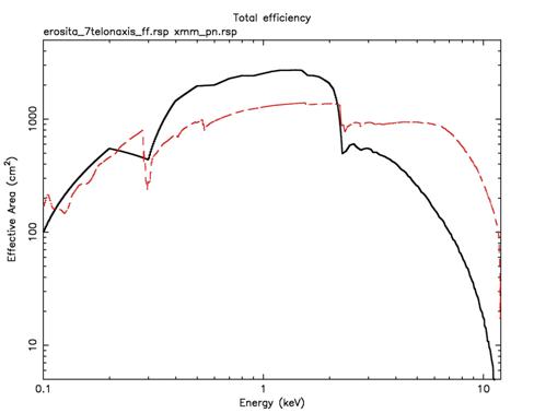
Figure 3.1.2: On-Axis effective area of 7
(thick black line) eROSITA telescopes with filter and CCD quantum efficiency
included. The effective area is compared with that of the XMM-Newton pn-CCD
camera (dashed red curve).
3.1.1.3
eROSITA
Surveys
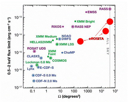
We
envisage the following surveys for eROSITA: An all-sky survey with about 1 year
integration time to discover obscured black holes and galactic sources, a
deeper, high galactic latitude survey to discover 50-100 thousand clusters of
galaxies and about 1 million AGN, covering 20000 deg2 in 3 years observation time and a
200-300 deg2 deep survey close to the south Galactic pole. Using the effective area
curve and assuming an observation efficiency of 60%, we estimate the following
survey sensitivities:
Summary of ROSITA Surveys:
|
Survey |
All-Sky
Survey |
Wide
Survey |
Deep
Survey |
|
Solid
Angle |
42000 |
20000 |
200 |
|
Exposure
time |
1
yr |
2.5
yrs |
0.5
yrs |
|
0.5-2
keV Smin AGN |
5.7´10-14 |
1.5´10-14 |
4´10-15 |
|
2-10
keV Smin AGN |
1.0´10-12 |
2.1´10-13 |
2.4´10-14 |
|
0.5-5
keV Smin Clusters |
1.6´10-13 |
3.3´10-14 |
8´10-15 |
|
0.5-2
keV AGN |
240000 |
800000 |
740000 |
|
2-10
keV AGN |
12600 |
84000 |
44000 |
|
Clusters |
32000 |
72000 |
6500 |
The
following figures compare these planned surveys with existing surveys.
3.1.2
Instrument
The
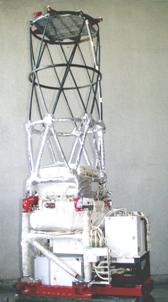
eROSITA X-ray telescope consists of seven mirror modules (Wolter-I optics) each
having its own CCD-detector in the focus. The basic structure of eROSITA is the
optical bench, a tube which carries at its front the seven mirror modules and
at its rear end the seven cameras. This concept was developed for the ABRIXAS
mission, which failed shortly after launch in 1999. On ABRIXAS, the seven
telescopes shared one large CCD camera; therefore the telescopes were tilted by
about 7° with respect to each other. The eROSITA mirrors will have larger
apertures, and their optical axes will be in parallel. Therefore the cameras
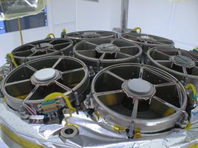
are separated into individual housings, giving the instrument a seven fold
redundancy (Fig. 3.1.3). The basic parameters of the instrument are given
in table 3.1.1.
Table 3.1.1
|
Fig. 3.1.3: schematic view of the eROSITA
telescopes with Wolter-I optics + baffles (grey) and the 7 CCD-cameras
including their (red) electronics boxes. |
number of mirror systems |
7 |
|
number
of nested mirror shells |
54 |
|
|
angular resolution |
<15² (1 KeV) |
|
|
energy range |
0.5 – 10 keV |
|
|
diameter of 1 mirror system |
358 mm |
|
|
focal length |
1600 mm |
|
|
material of mirror shells |
nickel |
|
|
mirror coating |
gold |
|
|
weight of 1 mirror system |
<50 kg |
|
|
detector principle |
pn-CCD |
|
|
size |
19.2×19.2 mm2 |
|
|
Pixel size |
75 µm × 75 µm |
|
|
read out speed |
50 msec |
|
|
energy resolution |
130
eV at 6 keV |
|
|
weight of each detector |
~14 kg |
|
|
Total weight of instrument |
~600 kg |
|
|
Size
(diameter / length) |
1.3 m / 2.6 m |
3.1.3
X-ray
Optics
Although
there are many possible configurations, only Wolter-I optics (paraboloid +
hyperboloid) have got real importance in X-ray astronomy. The ABRIXAS mirrors
also had this geometry. We will copy them for eROSITA with reducing the risk of
a new development. In order to enhance the effective area at low energies, we
will add 27 outer shells thereby doubling the diameter of the mirrors. We note
that the (smaller) ABRIXAS mirrors are already qualified. Each of the mirror
systems contains 54 nested shells. The focal length is 1600 mm. The
on-axis resolution is 15'' (half energy width, HEW). The geometry of the mirror
systems is optimized in order to achieve maximum sensitivity between 0.5 and 10
keV.
The optical design of the mirror modules requires shells with a wall
thickness between 0.2 and 0.4 mm and diameters between 76 and 358 mm. The
length of the paraboloid-hyperboloid pairs is 300 mm. Such mirrors are
fabricated using a nickel-galvanoplating process similar to the one used for
XMM-Newton. In order to enhance the reflectivity, all mirrors are coated with
gold.
|
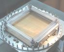
Figure 3.1.4: The entrance
apertures of the seven telescopes (ABRIXAS flight model). |
Like on
ABRIXAS the mirror systems still have the hexagonal geometry but are no longer
tilted with respect to each other.
Baffle: The baffles are tubes in front of each mirror
system in order to suppress any direct stray light into the mirror system. They
do not have any influence on the X-ray performance of the telescope. Their
length is 600 mm.
Camera(s): eROSITA will carry seven
individual CCD-detectors, each mounted in its own housing and equipped with its
own electronics (in a separate box). The CCD size of 19.2×19.2 mm2 corresponds
to a field of view of 41.2¢×41.2¢. The CCDs have to be cooled down to
-60°C for optimum operation and energy resolution.
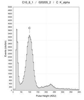
|
Figure 3.1.5: Clearly resolved C Kα peak, measured with
the novel eROSITA CCD. |
Figure 3.1.6: CCD module with
a frame store pn-CCD, connected to 2 CAMEX-chips. Everything is mounted onto
a ceramic carrier which, in turn, will be mounted to the cold plate (adapter
seen). |

Detector: During the last 18 years MPE has
developed in the semiconductor laboratory the cameras for XMM-Newton and
ABRIXAS based on the pn-CCD principle. The camera on XMM-Newton has been
operated successfully since early 2000. The eROSITA CCD are already fabricated;
they are an advanced version of the pn-CCD with smaller pixel sizes (75´75 µm2 instead of
150´150 µm2) and faster
readout. The latter is achieved by combining the proven technology with a frame
store area.
First
tests with these novel devices show quite promising resu
Cooling: We aim for passive
cooling (by means of heat pipes and a radiator), temperature control is
performed by means of heaters. The radiator concept has still to be worked out
because it critically depends both on the configuration of all instruments as
well as the mission scenario.
eROSITA Electronics: Figure 3.1.7 illustrates the internal system architecture of the electronics. Each of the seven detector modules has its own front-end electronics which comprises the processing of the primary event data and the control of the CCD. The latter («Sequencer») includes the proper timing for the parallel read out of the CCD via the multiplexer-chips («CAMEX») and the adjustment of all necessary voltages. The «Camera Electronics» provides the signal-filtering, the rejection of events induced by minimum ionizing particles (MIPS) and the recognition of «real» events, also when split among a group of adjacent pixels. A variety of tables (offset-map, noise-map etc. are calculated by the event processor and kept in memory. The CPU will be a signal processor (type: SMJ320C6203).
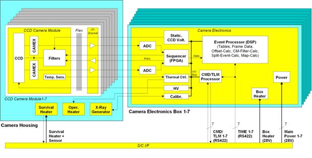
Figure 3.1.7: Architecture of the electronics
The «Control
Unit» is the central unit providing all interfaces to the camera head electronics,
collecting all information from the other units (HK, event data) as well as the
commanding of these units. eROSITA interfaces to the spacecraft via 7
individual lines (data and power).
Star
Sensor: eROSITA
needs star-trackers information (for post-facto analysis only).
Frontdoor: A front cover door is probably
needed for contamination reasons on ground and during launch. During the
mission it will serve as sunshield.
3.2 Lobster
3.2.1
Science
The goal
of Lobster, as for any ASM, is to approach the limit of «all the sky, all the
time». The instrument consists of six «lobster eye» MCP telescopes,
collectively providing wide angle (22.5º´162º) X-ray imaging in the
0.1-3.5 keV energy band, covering almost the entire X-ray sky once per 90
minute ISS orbit. For comparison, the instantaneous fields-of-view of
XMM-Newton and Chandra are less than 1 degree diameter. All-sky coverage is
provided in a straightforward way by the motion of the spacecraft, whose
orbital period is synchronous with the period of rotation about its alpha axis.
The goal of the mission is address the variability of the X-ray sky with
order-of-magnitude better sensitivity (~0.15 mCrab in one day, 5s) and angular resolution than any previous (or
indeed feasible) non-imaging ASM. The scientific impact of Lobster-ISS spans
all of astronomy - from studies of the X-ray emission of comets to stars and
quasars, from regular X-ray binaries to erratic stellar transients (~4 000
per year at a flux level of 10-10 erg cm-2 s-1
and ~36 000 at 10-11 erg cm-2 s-1), from
the energetically gentle fluctuations in the hot outer regions of stars to the
catastrophic events of supernovæ and the enigmatic gamma-ray bursts (GRBs
- more than 1000 GRBs per year out to z ~4). Most importantly, about 400 bright
AGN will be monitored at the 20% level on a daily basis for the duration of the
mission, providing the first true census of X-ray time variability in active
galaxies, and providing a definitive answer as to whether characteristic
timescales exist in such sources. About 30 AGN are bright enough at any given
time to allow daily monitoring with Lobster to ~5% accuracy, forming a «core
sample» which is ideal for multi-wavelength monitoring campaigns. An important
secondary function of Lobster data analysis, as with any X-ray ASM, will be to
alert contemporary narrow-field-of-view X-ray observatories. The final Lobster
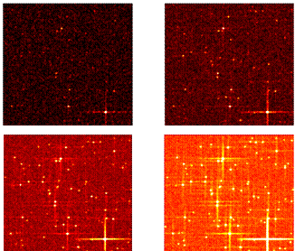
catalogue will contain some ~250 000 sources. Fig. 3.2.1 shows the
simulated Lobster images of a 10 ´ 10 sq.degree field at high
galactic latitude, after elapsed times (clockwise from top left) of 1, 5, 25
and 125 days.
4 3 2 1
Figure 3.2.1. simulated Lobster images of
a 10°×10° field at high
galactic latitude, after elapsed times (clockwise from top left) of 1, 5, 25
and 125 days, based on data from the ROSAT all-sky catalogue.
3.2.2
Instrument
Lobster
is an all-sky X-ray monitor comprising of six telescope modules, each
consisting of approximately 60 Microchannel Plate (MCP) optics, tiled to
produce the required field of view and geometrical area. Each telescope module
has a Microwell array proportional counter detector in the focal plane.
The basic
structure of Lobster is shown in figure 3.2.2. The basic parameters of the
instrument are given in table 3.2.1. Note that both figure and table describe
the original configuration of Lobster, which was a design for deployment on the
International Space Station. In particular, no Gamma Ray Burst Monitor (GRBM)
will be required in the SRG configuration since a GRBM is already specified in
the overall mission design. The six telescope modules are aligned to produce a
single, contiguous field of view of 165°´22°; the motion of the spacecraft
platform sweeps this FOV around the sky once per orbit to build up the all-sky
map. Note that the 165° field width is a
result of volume constraints in the ISS configuration and may be increased to
180° in the SRG design. A number of smaller subsystems are provided to
support the core instruments (star trackers, sun sensor and particle monitor).
Mass and power requirements are provided in tables 3.2.2 and 3.2.3.
Table 3.2.1.
Instrument characteristics in the original ISS configuration
|
Fig. 3.2.2: Schematic view of
the Lobster instrument in the original configuration designed for the ISS. GRBM
will be omitted for the SRG mission, which carries its own monitor. |
number of telescope modules |
6 |
|
number
of MCP optic tiles |
~60 per module |
|
|
angular resolution (FWHM) |
4¢ |
|
|
Field of view (1 module) |
27.5°´22° |
|
|
energy range |
0.1 – 4.0 keV |
|
|
focal length |
375 mm |
|
|
Reflectivity coating |
Gold or Iridium |
|
|
detector principle |
Microwell array |
|
|
Size |
20×20 cm2 |
|
|
Pixelsize |
200 µm diameter |
|
|
read out speed |
0.1 sec |
|
|
energy resolution |
~1.2 keV |
|
|
Instrument mass |
120 kg |
|
|
Data volume |
~5.6 Gbit/day |
MCP X-ray optics: Lead-glass plates containing a square array of
square cross-section holes or channels. The square sides are 40 mm long
and the plate thickness is 1 mm. X-rays may be reflected at grazing
incidence, from the inside surfaces of these channels; the reflectivity of
these channel walls will be enhanced by the deposition of a nickel, gold or
iridium coating. The plates, initially flat, are curved or «slumped» to a 0.75 m
radius spherical figure. In this way X-rays from a distant object can be
focused to a point. Each optic module is a 6´8 square array of MCP tiles and
forms the top surface of a telescope module. Each MCP optic is aligned by
(visible-light) optical means and fixed to a beryllium alloy optic module
support structure using a quasi-isostatic design. This support structure is
also spherical, with radius 0.75 m. The anticipated bonding method is UV
curing epoxy adhesive. An MCP-to-MCP alignment variation of 1¢ (RMS) is tolerable for the overall 4¢ resolution goal of the instrument. The
structure shall be constructed from materials which minimize thermal gradients
(i.e. a quasi-isothermal structure) to minimize thermally induced bending of
the structure.
Figure 3.2.3: Effective area for Lobster, with Nickel reflectivity
coating.
Microwell array detectors.
These are a
very robust and stable type of gas-filled proportional counter X-ray detector.
Their history can be traced back to the very first Geiger counters used to
detect ionizing radiation. The detector is a gas cell with an electric field
applied across it. The cell has a thin window through which X-rays may enter.
The well array is manufactured by laser-drilling holes in a flexible kapton
substrate. There are three electrodes in the system, one on the detector window
and one on either side of the kapton. X-ray photons cause ionization of the gas
and the electric field causes the electrons produced to drift down towards the
array. Within the wells there is a region of much higher field strength and
acceleration sufficient to cause an electron avalanche by repeated, multiple ionizations. The result is a detectable
signal collected on the electrodes at the top and bottom of the well. The
electrodes are connected to pre-amps in such a way that the well in which the
avalanche falls can be identified and, hence, the entry position of the
detected photon localized. The voltages on the electrodes are set so that the
output signal is proportional to the number of electron-ion pairs produced in
the initial interaction between the X-ray photon and the gas. In this way an
energy resolution of DE/E ~ 20%
is achieved. The detector works in the same way as a conventional multi-wire
proportional counter except that the avalanches are localized in the wells. The
advantage of electrodes deposited by printed circuit technology on the kapton
is relative simplicity, stability and scalability.
Although
they operate using the same principles as traditional wired proportional
counters, the architecture of the microwell arrays is less susceptible to heavy
ion damage. Since the high field region is very small (i.e. limited to the well
depth, approx. 0.25 mm) the spark is contained within a limited area of
the detector and, in the worst case, a damaged region will be limited to a
single microwell.
The focal
surface of each optic array is a 20´20 cm2 section of a
sphere. However, as the required angular resolution of the instrument is only 4¢, some position error in the detectors is
allowable. We can, therefore, approximate the focal surface by tiling it with
four 10´10 cm2 detectors,
with planar well arrays, arranged in a pyramid. Each of these detectors has a
window (and hence drift electrode) with four p
Lobster Electronics: Fig. 3.2.4 illustrates a
possible configuration for the internal system architecture, defined for the
original ISS configuration. All control of the six microwell detectors is via
the Detector Interface Unit (DIU). Data from the environmental sensors (sun and
particle detectors) is processed by dedicated electronics (which, in the case
of the particle detector and sun sensor, are incorporated into the sensor
unit), and passed to the DIU, which can shut down detector power selectively
(i.e. a single detector at a time for solar avoidance) or globally (to protect
against high particle backgrounds during ISS passages through the SAA). Signals
from the GRB monitor (GRBM) and star trackers are not required as input to the
telescope modules, but are processed in the DPU. High priority events are
flagged for telemetry during the next available «telescience» downlink. Due to
the need for rapid burst source localization, on-the-fly aspect reconstruction
of images from the Lobster-ISS telescopes is required. Data from the star
trackers are therefore passed to the DPU and used to deconvolve the motion of
the ISS platform from the X-ray telescope images.
Figure 3.2.4: Internal system architecture
Star
Tracker:
Lobster uses star trackers to provide data for aspect reconstruction of X-ray
telescope images. On-board aspect reconstruction of X-ray telescope data will
be required when an event designated as «high priority» is detected, such that
the location of the source can be rapidly identified and transmitted to ground
via the continuously available «telescience» link.
Sun Sensor: Owing to the ISS orbit and Lobster-ISS configuration there will be
periods of time when the sun shines into one, or more, of the Lobster telescope
modules. At these times, there is a requirement to cut the detector HT to the
appropriate detector(s). Failure to do so may result in detector breakdown and
possible loss of (part of) a telescope module. ISS attitude at any one time is
somewhat uncertain, so programming solar ingress times in advance will be
imprecise. As a result a sun position sensor is necessary. The sensor must be
positioned such that its field of sensitivity leads the Lobster telescope field
of view to allow adequate warning of solar ingress into the field of view of
the MCP optics.
Space
qualified sun sensors are available, commercially, within Europe from
Jena-Optronik GmbH in
Particle Monitor: A particle monitor is included as a precaution against the high particle
flux the instrument will experience during transits of the SAA, at which time
the detectors are protected by lowering the HT to zero as prolonged operation
at high rates of particle events will cause deterioration of the detectors.
Various off-the-shelf models are available, and the Lobster consortium also has
the capability to build a custom made, low-cost proton counter (based, for
example, on Channel Electron Multiplier technology). Timing information can
also be used to initiate power-down procedures for SAA passages.
Digital Processor Unit: The DPU provides Lobster with the computational
capability required to perform on-board aspect reconstruction and source
location in the event that a «high priority» event is detected. It incorporates
a mass storage device to store normal science data during the periods between
downlinks.
Thermal Control Hardware: Thermal control is self standing (no thermal
control from equipment external to the payload is required. Electrical heaters
situated in the MCP optic arrays between the corners of adjacent MCPs provide
heat while the arrays are in shadow, to reduce the thermal gradient across the
optics. 40 W of heating power is reserved for this purpose. In addition,
an estimated 10 W of additional power is included for thermal control of
electronics subsystems. Current estimates suggest that radiators are not
required in the thermal control subsystem.
Support Structure: The support structure holds the optics in the correct position, relative
to the local zenith. This structure includes a wedge-shaped base and the six
skeletal telescope modules. The focal plane detectors and MCP optics are
mounted onto this structural element. The structure consists of a CFRP «carapace»,
with a wall thickness of 1.5 mm. The CFRP is a filament wound, 5/95
degrees symmetrical lay-up with T300 adhesive and epoxy resin. Invar bars
maintain the correct optic-to-focal plane distance; these bars have
Table 3.2.2. Lobster mass
budget, based on the original ISS configuration of the instrument.
|
Item |
Mass (kg) |
Contin. (%) |
Mass (inc. contin.) |
|
Support Structure |
45 |
10 |
49.5 |
|
Lobster eye optics |
5 |
10 |
5.5 |
|
Focal pl |
19.5 |
10 |
21.4 |
|
Detector interface unit |
1 |
30 |
1.3 |
|
DPU-PDU |
16 |
35 |
21.6 |
|
Instrument harness |
2 |
40 |
2.8 |
|
Instrument thermal control subsystem |
6 |
35 |
8.1 |
|
Sun sensor |
0.25 |
10 |
0.275 |
|
Particle detector |
1 |
10 |
1.1 |
|
Star trackers |
7.4 |
0 |
7.4 |
|
Total
Instrument Mass |
|
|
119.0 |
Table 3.2.3. Lobster power
budget, based on the original ISS configuration of the instrument.
|
Unit |
Power
(W) |
Contin.
(%) |
Power
(inc. contin.) |
|
Support
Structure |
0 |
10 |
0 |
|
Lobster
eye optics |
0 |
10 |
0 |
|
Focal pl |
14 |
10 |
15.4 |
|
Detector interface unit |
1 |
30 |
1.3 |
|
DPU-PDU |
36 |
35 |
48.6 |
|
Instrument harness |
0 |
40 |
0 |
|
Instrument thermal control subsystem |
50 |
35 |
67.5 |
|
Sun sensor |
1 |
10 |
1.1 |
|
Particle detector |
1.5 |
10 |
1.65 |
|
Star trackers1 |
9 |
0 |
9 |
|
Total
Instrument Power |
|
|
144.55 |
1Only one star tracker will be powered at any given time.
3.3 ART
3.3.1
Science
ART
instrument is designed for the following tasks:
-
Extend
the energy coverage of the SRG observatory up to 120 keV;
-
Search
for heavily absorbed /
-
Provide
a necessary high energy extension of AGN spectra to allow detailed modeling of
their spectra, including reflection component;
-
Provide
the information on the hard tails in the spectra of galaxy clusters to
constrain the strength of the magnetic fields in the inter cluster medium;
-
Study
broad band spectra of Galactic objects (including binary systems, anomalous
pulsars, supernova remnants);
-
Study
non-thermal component in the Galaxy diffuse emission.
3.3.2 Instrument
A set of
four coded mask telescopes with two of them operating in 20-120 keV (ART-HX)
and the other two in 3-30 keV energy range (ART-X). Field of view of each
telescope is 10°´10°. Angular resolution is £3¢ for ART-X and £9¢ for ART-HX. Telescopes are binned in two
pairs, each pair constituting a module of 1´0.5´2 meter size and
-
carry
out all-sky surveys in 3-120 keV energy range synchronous to ROSITA telescope and
Lobster wide-field monitor;
-
perform
observations of various sources in the Galactic plane during the deep surveys of
the sky areas near galactic poles by ROSITA telescope.
It is
planned to make use of the detector based on pixel array based on semiconductor
CdZnTe crystals in ART-HX telescope (prototypes are ISRGI/Integral and
BAT/SWIFT) and gas filled position sensitive counter in ART-X telescope
(prototypes are ART-P/Granat, WFC/BeppoSAX, TTM/Mir-Kvant).
|
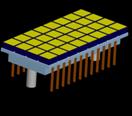
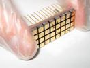
Fig. 3.3.2: ART-HX, CZT detector plane based on 128
MXDM (4096 CZT crystals) 300´300 mm |
Layout of Multielement X-Ray Detection Module (MXDM) |
Energy
range 20-120 keV FOV
10°´10° Angular
resolution £9¢ Energy
resolution £3 keV at 60 keV |
|
Laboratory model of MXDM |
||
|
Am241 spectrum with MXDM |

|
|
|
Energy
range 3-30 keV FOV
10°´10° Angular
resolution £3¢ Energy
resolution £1.2 keV at 6 keV |
|
|
||
|
|

The area
of each detector is about 103 cm2.
3.4 GRB detector
The Gamma
Ray Burst Monitor (GRBM) will provide timing, spectral and (rough) localization
of GRB (and other classes of hard X-ray transients, such as Soft Gamma-Ray
Repeaters) by covering the range 5-300
keV (TBC) and a field of view overlapping the LOBSTER FOV with the goal of:
-
identify
classical GRBs from other fast transients detected with LOBSTER, through timing
coincidence and rough position localization (a few degrees TBD);
-
provide
wide band spectra of GRB to determine the peak energy, and low energy
absorption column density. Study the broad band spectral evolution with time.
4.
Launch
vehicle
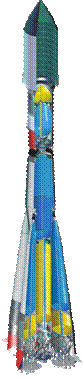 Soyuz launch vehicle is proposed for
the delivery of SRG project. For the launch from Kourou that will be Soyuz-ST,
in case of launch from Baikonur – Soyuz-FG or Soyuz-2a/b.
Soyuz launch vehicle is proposed for
the delivery of SRG project. For the launch from Kourou that will be Soyuz-ST,
in case of launch from Baikonur – Soyuz-FG or Soyuz-2a/b.
Soyuz-FG
rockets are the primary launch vehicles among Russian family of launchers. They
are delivering into orbit the lion’s share of spacecrafts in frameworks of
Federal Space Program of RF and the program of international collaboration in
space.
Russia is
developing Soyuz-2 rocket intended for the delivery of autonomous spacecrafts
into low, middle, high, sun-synchronous, geo-transfer and geostationary orbits,
as well as for manned and cargo spacecrafts within the International Space
Station program.
Development
of Soyuz-2 launch vehicle is carried out in two steps: phase 1a and 1b.
During the modification phase 1a new control and telemetry systems, as
well as modified first and second stage engines will be used. At the
phase 1b a new engine with increased total impulse will be installed on
the third stage.
Nose-cones
of the following diameters can be used with Soyuz-2 rocket: 2.7, 3.0, 3.3, 3.7
and 4.11 m. The 11.4 m long nose-cone of 4.11 m diameter is
under construction.
In order
to provide launches from Kourou cosmodrome the modified Soyuz-ST rocket adapted
for use at Kourou is under development based on Soyuz-2a/b.
4.1
Soyuz LV
|
Parameters |
SOYUZ-FG |
SOYUZ-2 |
||
|
phase A |
phase B |
|
||
|
Length (m) |
42.5 |
44.3 |
44.3 |
|
|
Diameter (m) |
10.3 |
10.3 |
10.3 |
|
|
Lift-off mass (t) |
302 |
305 |
305 |
|
|
Number of stages |
3 |
|||
|
Propellant |
O2+Kerosene |
|||
|
1st stage engine |
RD-107 |
RD-107 |
||
|
2nd stage engine |
RD-108 |
RD-108 |
||
|
3rd stage engine |
RD-0110 |
RD-0110 |
RD-0124 |
|
|
Avionics |
analogue type on 2nd and 3rd stages |
unified digital avionics on the 3rd stage |
||
|
Status |
in operation |
under development |
||
|
Performance from Baikonur* (kg) |
7130** |
7020*** |
8250*** |
|
* LEO,
4.2 FREGAT payload assist module
For final
insertion of
|
Characteristics: |
|
|
|
Height
(m) |
1.5 |
|
|
Diameter
(m) |
3.35 |
|
|
Dry
mass (kg) |
970 |
|
|
Total
mass with propellant (kg) |
6635 |
|
|
Propellant |
UDMH/N2O4 |
|
|
Main
engine thrust (kN) |
19.6 |
|
|
Re-ignition
capability |
up
to 20 |
|
|
Lifetime
(hours) |
up
to 48 |
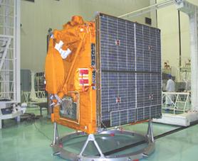
5. Satellite BUS
Medium
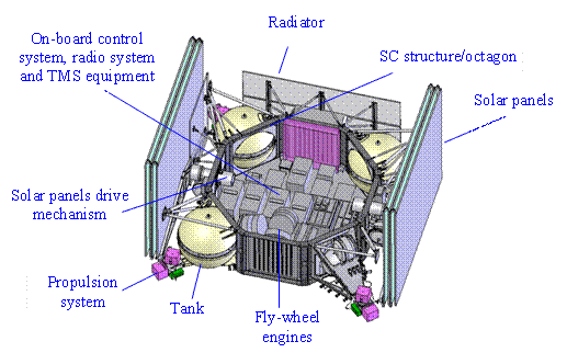
class spacecraft would be suitable for the mission, such as Yamal (RSC Energia), which has been operated in space,
or Navigator (Lavochkin
Association). Both platforms are three-axis stabilization.
5.1 Yamal (RSC Energia)
5.1.1
Status
In
operation, Yamal-100 since 1999, Yamal-200 since 2003.
5.1.2 Main characteristics
|
Mass |
Up
to |
Generic
Yamal - 100 Satellites Bus. Launch and operation since
|
|
Payload
mass |
Up
to |
|
|
Payload
power consumption (including payload thermal system) |
Up
to 1200 W |
|
|
Orientation
accuracy |
1.5¢ |
|
|
Stabilization
accuracy: Angular angular
rate |
30² 10-4 °/s |
|
|
Retargeting
rate, °/min Nominal maximum |
0.05…0.1 0.4 |
|
|
Life
time |
Up
to 10 years |
5.2 Navigator (Lavochkin Association)
5.2.1
Status
Under
development, first flight test is planned for 2007.
5.2.2
Main
characteristics
|
SC
dry mass |
|
|
Propellant
(hydrazine, helium) |
|
|
Navigation
and stabilization parameters: Pointing Stabilization stabilization
average velocity maximal
re-orientation velocity |
2¢ ±2.5² 0.36²/sec 0.25°/sec |
|
Power
supply system parameters: supply
voltage Science
equipment unit power |
27 ± 1.35
V 500 W |
|
Lifetime |
5 years |
5.3 On-board radio complex
It is considered to install European on-board radio system similar in
characteristics to the radio complex manufactured by SystemTechnik Taubenreuther STT,
Transmitter:
|
Frequency range |
2200
.. 2290 MHz |
|
Antenna output transmitting power |
+36 dBm (+2 dBm / - 0 dBm) |
|
Transmitter modulation |
BPSK 4 Mbps |
|
Power
consumption |
£ 30 W |
Receiver:
|
Frequency
range |
2025 .. 2110 MHz |
|
Frequency |
2058 MHz |
|
holding range |
±100 kHz |
|
Error
bit rate |
Less than 10-6 @ –105 dBm |
|
Receiver
demodulation |
BPSK 256 kbps |
|
Power consumption |
£ 3 W |
|
Receiver
sensitivity |
-105
dBm min @ error bit rate = 10-6 |
Antenna:
|
Polarization |
circular / RHC |
|
Covering |
Hemispherical |
|
Power |
max. 40dBm CW |
|
Impedance |
50 W |
|
Operational
temperature |
-40° … + |
|
Uplink
frequency range |
2025 … 2110 MHz |
|
Downlink
frequency range |
2200 … 2290 MHz |
6.
Mission main phases
6.1 From Kourou
-
SC
insertion by Soyuz-2 LV from Kourou launch
into
-
Space
head module (SHM)
separation from
-
Fregat PAM 1st ignition, characteristic velocity (V1 = 110 m/sec) performance and
insertion of
-
Fregat PAM 2nd ignition, characteristic velocity (V2 = 107 m/sec) performance and
insertion of
-
-
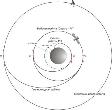
6.1.1 Orbital parameters
-
height
-
- inclination £5°;
- orbital period 96 min;
- maximal shadow duration 35 min.
6.2 From Baikonur
-
SC
insertion by Soyuz-2 LV from Baikonur launch
into
-
Space
head module (SHM)
separation from
-
Fregat PAM 1st and 2nd ignition, insertion of
-
6.2.1 Orbital parameters
-
height
-
- inclination 29°;
- orbital period 96 min;
- maximal shadow duration 35 min.
7.
Ground
segment
Structure:
-
SC
-
ESA
Ground Station (
-
Italian
Ground Station (
Visibility
intervals from Kourou or Malindi ground station 8 – 11 min.
There are
other possibilities concerned to ground stations in the case of launching from Baikonur.
8.
ADDITIONAL
PL MASS
In the
preferred case of the Kourou launch, a second satellite launch, including the
possibility of a geostationary orbit, could be offered to supplement funding
for the launch.
|
Orbit parameters |
|
Maximum dimension |
Satellite applications |
|
Circular
orbit: H = 580 km, Inclination £5º |
5600
(with Fregat PAM) |
H = 1000 mm,
diameter = 1800 mm |
Telecommunication,
for Earth remote sensing, Technological experiments |
|
Geostationary
orbit |
800 |
Telecommunication,
Meteorological |
|
|
Elliptical
orbit: Hp = 580 km, Ha = 300000 km, Inclination
£5º |
1200 |
Scientific |