
Russian-Turkish 1.5-m Telescope

(C) Copyright
HEAD
IKI
Guides and finders
Photoelectric guide
Photoelectric guide consists of tube and photoelectric head.
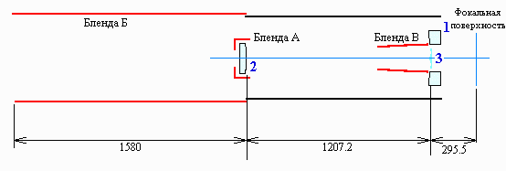
Guide is built on Cassegrain optical scheme. The main mirror 1 reflects
light to the secondary mirror 2 which collects it in the focal plane of system.
To improve image quality lens corrector 3 is placed between focal plane and
secondary mirror. Blends A, B and C fully remove dispersed light. The system
is thermally stable due to usage of quartz as a material for optical parts
and thermally stable connection based on invar. That allows to maintain the
constant air volume between primary and secondary mirror during the daily and
season temperature changes at the observatory.
| Primary mirror diameter, mm |
|
| Focal length, mm |
|
| Focal ratio |
|
| Linear field of view, mm |
|
| Angular field of view |
|
| Central screening area, % |
|
| Concentration of light energy at 632.8 nm wavelength on the optical axis within the circle of diameter | |
| 0.036 mm, %, at least |
|
| The same at the edge of field of view, at 40 mm from optcal axis within the circle of diameter | |
| 0.036 mm, %, at least |
|
The tube has a blend at the front side which is attached to it with the aid of hinge and shutter. It can be moved aside during the changing the secondary mirrors of the telescope. Blend has the door with electro-mechanical drive which is operated from the telescope control station.
Photoelectric head includes modulator, block of photoamplifier and optical-mechanical system represented by narrow field (2mm) lense placed on two slides for its motion within guide FOV. Slides motion directions are mutually perpendicular, X axis corresponding to image motion along hour angle (right ascension) and Y axis - along declination.
Range of narrow-field lens motion along X and Y axes covers +/-40 mm from the average value that corresponds to the position of photoguide line of sight parallel to the telescope line of sight. X and Y slides have optical rulers with 1 mm step and raster grids which provide 0.01 mm readout accuracy. Kellner eyepiece with focal length of 56 mm is placed at the outer side of the focal part of photoguide. Guide star and central cross can be seen through this eyepiece. The second eyepiece with 28 mm focal length is also available for X and Y values readout. For the observer's convenience position of this eyepiece can be changed using the optical knuckle.
Control of X and Y slides motion is provided by the special key from the tools set. The plug connector for it is located at the photohead.
Besides that, the assembly carries the following items:
- Switch for changing the position of diagonal mirror from V (visual guiding) to PH (photoelectric guiding).
- Two toggles for switching the light in central cross of eyepiece and readout scales of X and Y slides motion.
- Two rheostats for adjusting the illumation level of X and Y readout scales and that of eyepiece grid.
- Plug connector for photoguide - telescope control system cable.